Phage
Contents
These are projects for phage / BM2013. If you ended up here and you're not part of phage, then fnord.
Phagelings: please record interest at this gdoc
Demo movie, click link to play (OGV codec; supported on chrome and firefox, if you have IE use something else):
http://bunniefoo.com/bunnie/phage-movie.ogv
Phage Band
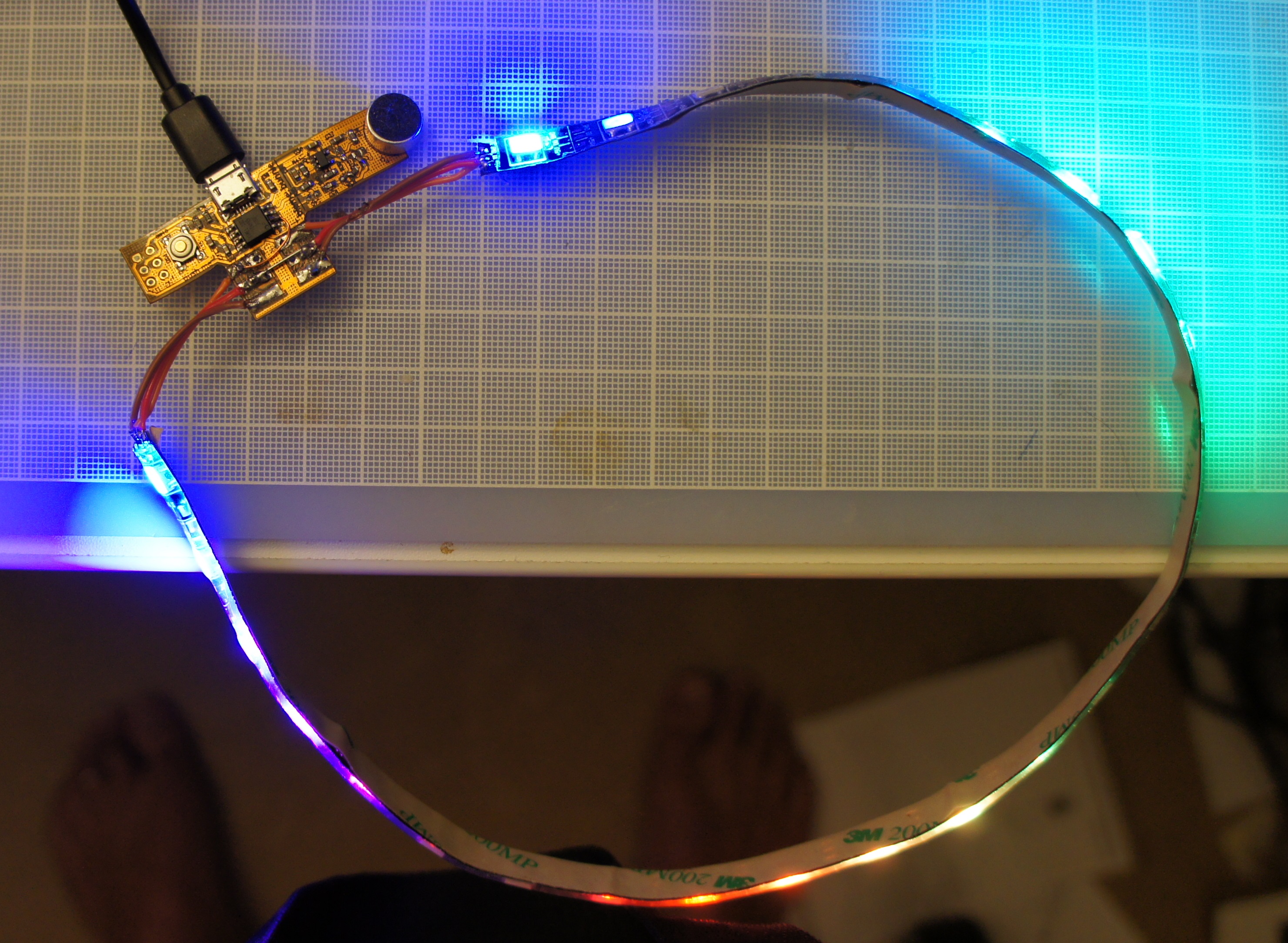
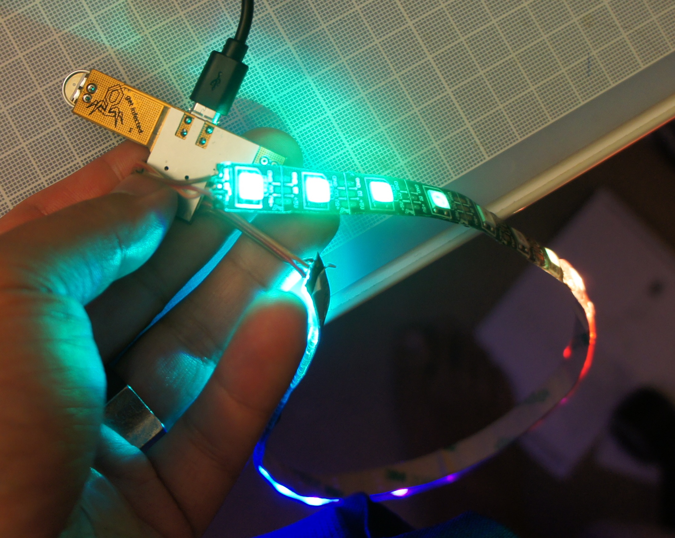
The phage band is a small flexible circuit board that's designed to be soldered in a loop of WS2812 RGB LEDs. It is about the size of your thumb.
It's meant to be a convenient and compact way to make a ribbon of LEDs do something interesting.
As of early July, the board has been sent out for fabrication and should be ready well in advance of BM2013.
The board has the following features:
- Powered off of +5V via microUSB header (for use with battery packs commonly used to charge cell phones)
- ATTiny85 for pre-programmed light patterns
- A single pushbutton to control operation mode
- If both ends of the WS2812 ribbon is soldered to the board, the ATTiny85 can automatically detect the length of the LED string
- Microphone and pre-amp with gain control selection (aka "robot heart mode")
- Flex circuit construction
- programming header and microphone section can be sheared off with scissors if they are not needed for a more compact driver circuit
- Steel stiffener plate under ribbon solder point and microUSB header for mechanical robustness
You can download schematics and board layout in PDF format at http://bunniefoo.com/bunnie/phage-armband.PDF
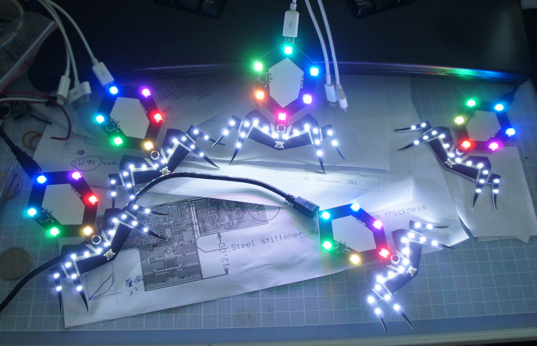
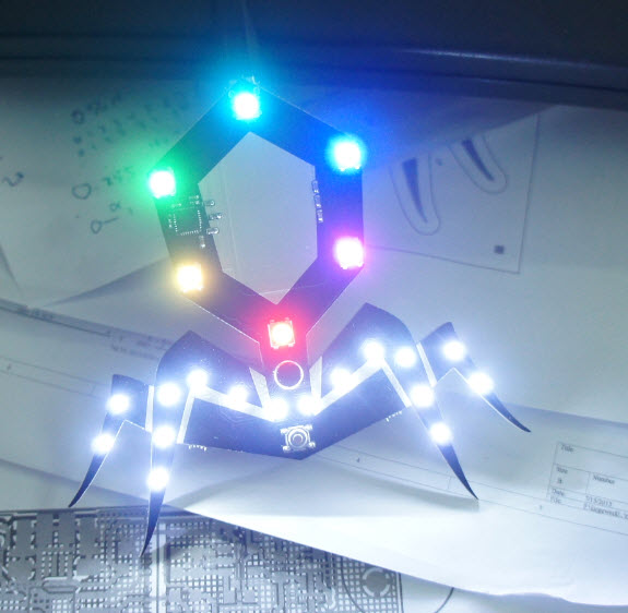
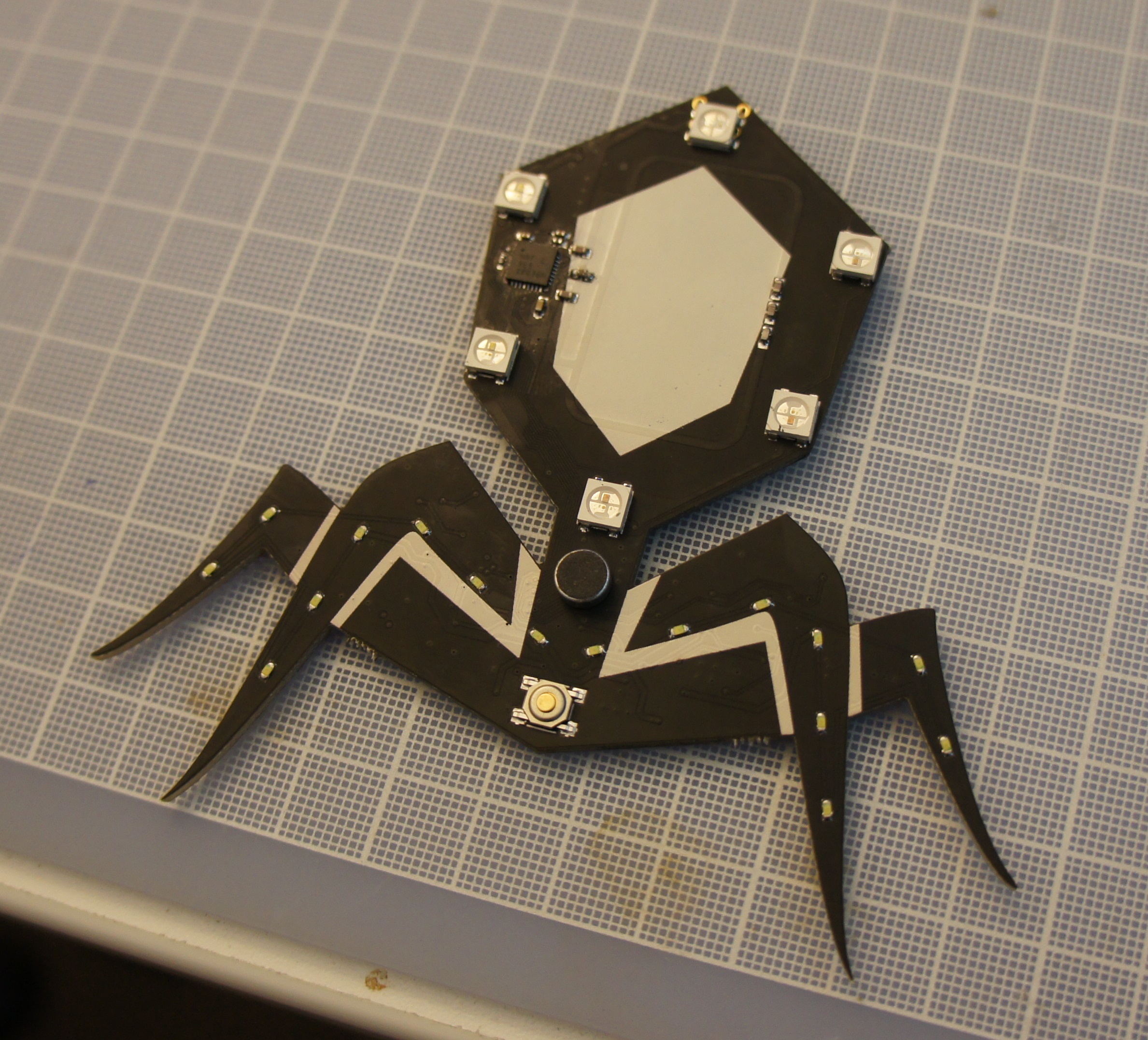
Some photos of the board:
Phage Locator
The phage locator is a design proposal. If enough phagelings are interested, I'll complete the design and get them built.
The idea of the phage locator is it's a little "badge" you can wear around. It has LEDs (of course), and it has a "locate" feature. When the button at the base of the board is pressed, an RF beacon is sent out. Any companions in the vicinity (20m range line of site) will pick up the beacon and start strobing.
When not in locate mode, the board cycles the lights, and has a microphone so it can react to sound. The sound behavior is fairly simple. In response to loud, continuous bass, the lights start to cycle faster.
Below are renderings of what the board might look like.
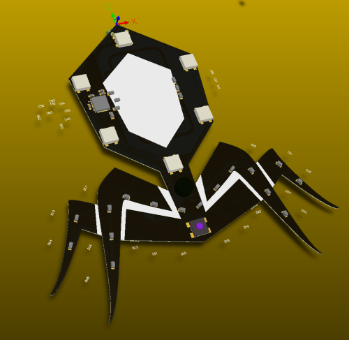
There are some components in the white silkscreen region of the head, unfortunately. Physics is a bitch, those were the dimensions of the loop antenna as writ. :P But, I think it's not going to be too intrusive. The head of the phage is also slightly larger than the standard logo; the whole system is sized basically around the loop antenna for making the comms work.
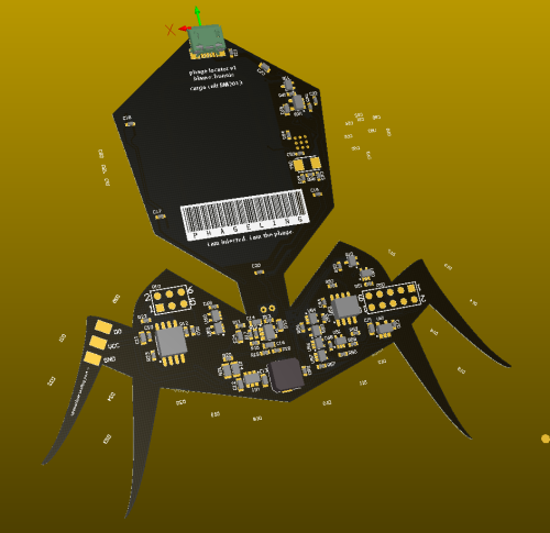
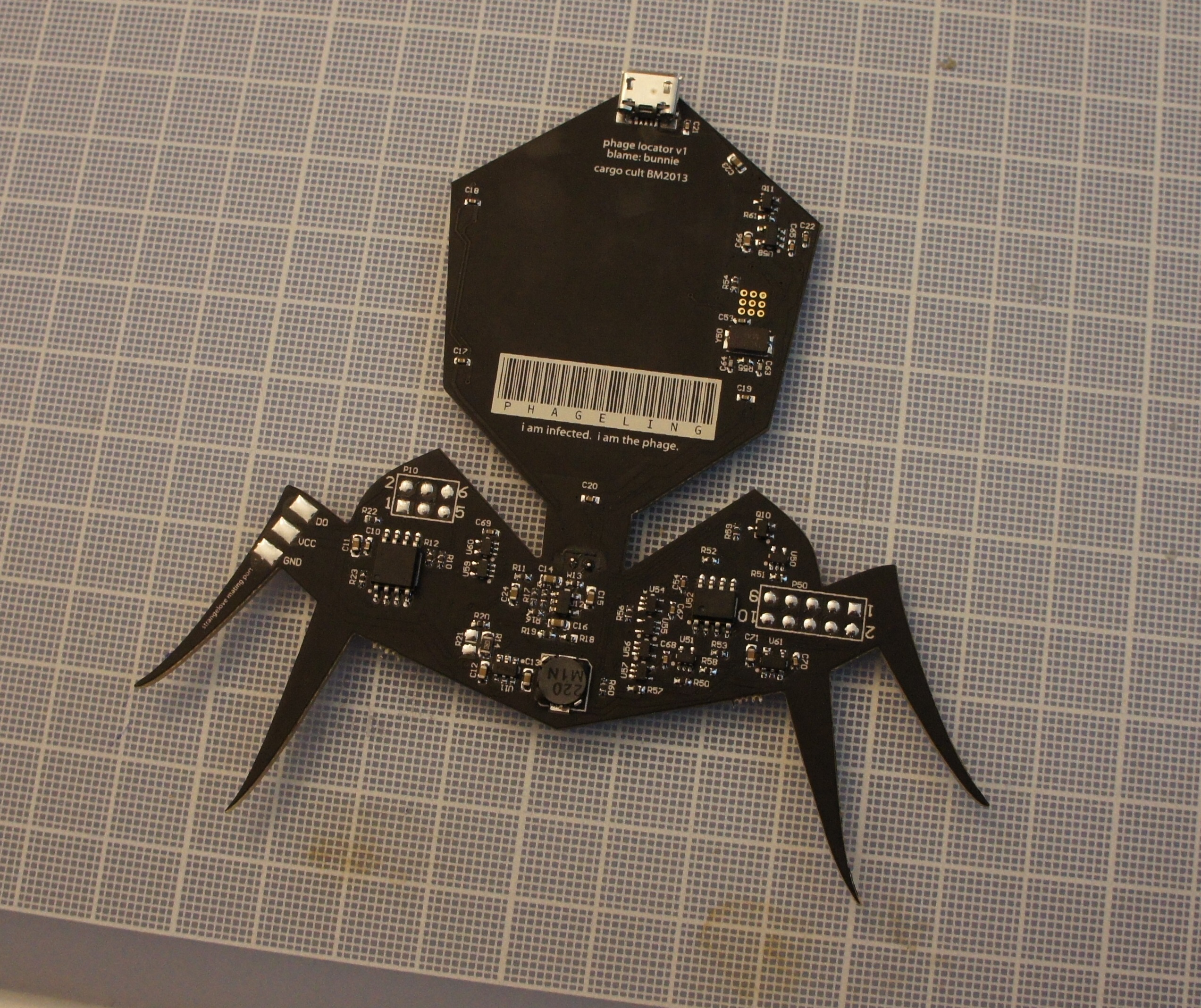
The back reads "PHAGELING [in code 39] / i am infected. i am the phage." and also says "cargo cult BM2013".
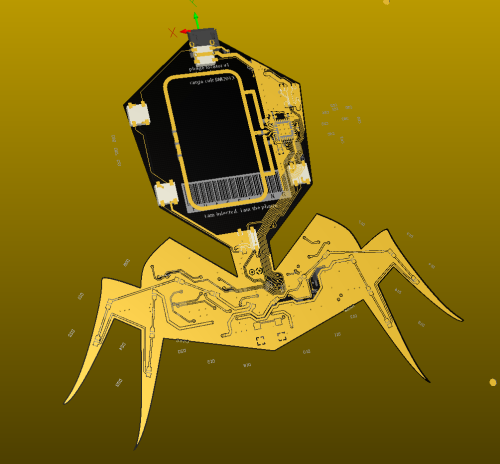
This cut-through of the board nicely shows the antenna loop. Let's hope my calculations work out and the reception is decent!
you can download schematics and layout in PDF format at http://bunniefoo.com/bunnie/phage-locator.PDF
Here is the feature summary:
- Powered off of +5V via micro-USB (compatible with most cell phone battery packs)
- 6 RGB LEDs around the capsid that can cycle independently as the primary LED mechanism
- RGB LEDs are controlled by an ATTiny85, so the same firmware patterns programmed on phage-armband can be directly ported into the badge and vice-versa. I was originally thinking about just using the 8051 inside the nRF9E5 to do all the control, but rapidly realized that would suck for people who wanted to make their own light patterns. The ATtiny85 can be programmed using an Arduino IDE if you have the correct adapter (see http://hlt.media.mit.edu/?p=1695)
- 16 white LEDs around the legs that cycle in a "gang" (i.e., all at once -- using a single boost converter to save power)
- RF beacon, activated by pushbutton
- RF receiver - causes strobing action when beacon is detected
- Microphone to cause lights to cycle in the presence of sound
- ~4" tall
- Made out of 1.6mm FR-4 PCB
- Matte black soldermask with white silkscreen, gold trim
- Solder tabs that allow you to attach WS2812 light strips to the locator in a permanent fashion. This means you can use the locator as an RF front end for large, fixed installations of LEDs (such as what might be on Strangelove). Because the locator doesn't operate on a loop of LEDs, you will have to burn a custom firmware on that encodes the length of the LED strand. I will have a laptop and a burner with me on the playa, and a system that can touch down onto the programming pads with spring-loaded pins so it should be quick & easy to do field upgrades of the light patterns and behavior.
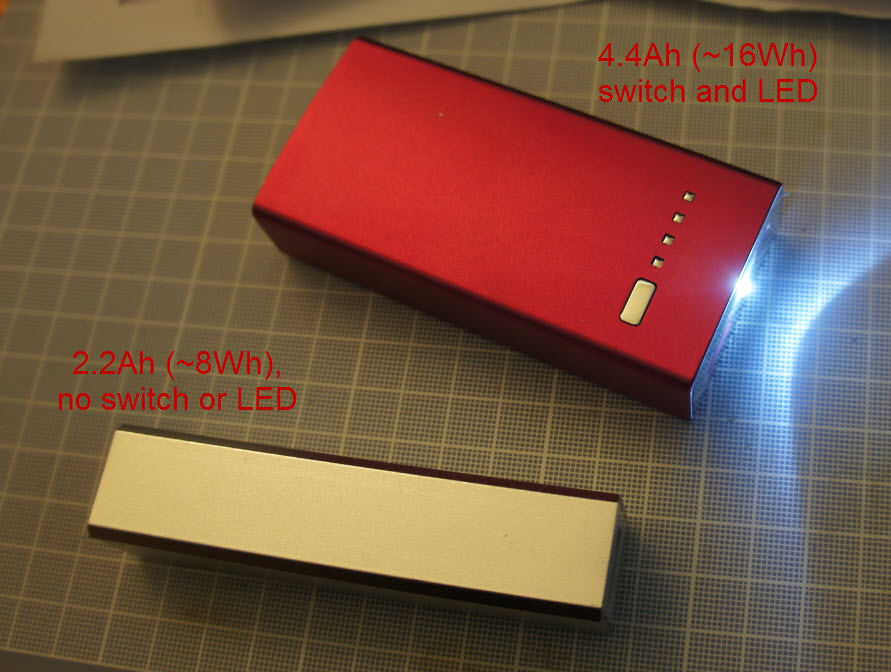
With a sufficiently modest light cycling pattern, it should last a day on a typical cell phone charging battery pack. Quiescent draw of radio in passive receive + other bits is estimated to be 20mA @ 5V. A conservative light cycling pattern (20% duty on, 50% brightness) will burn about 50mA @ 5V time-average. So about 70mA-100mA estimated current draw, or 350-500mW. A small "lipstick" style cell phone charger pack will have about 9Wh capacity. That's ~18-25 hours run time. Of course, the primary source of current draw is the light pattern. A full-on pattern will draw about 200mA @ 5V, or 1Wh; just idling with lights off waiting for a signal, it draws 0.1Wh. So that's a 10:1 change in runtime based upon the light pattern you choose.
A fully charged 2200mAh battery pack will power the badge in idle mode (no strobing) for about 12 hours. That'll probably cover you from when you go out till sun-up at the very least.
Cost is $40 per.
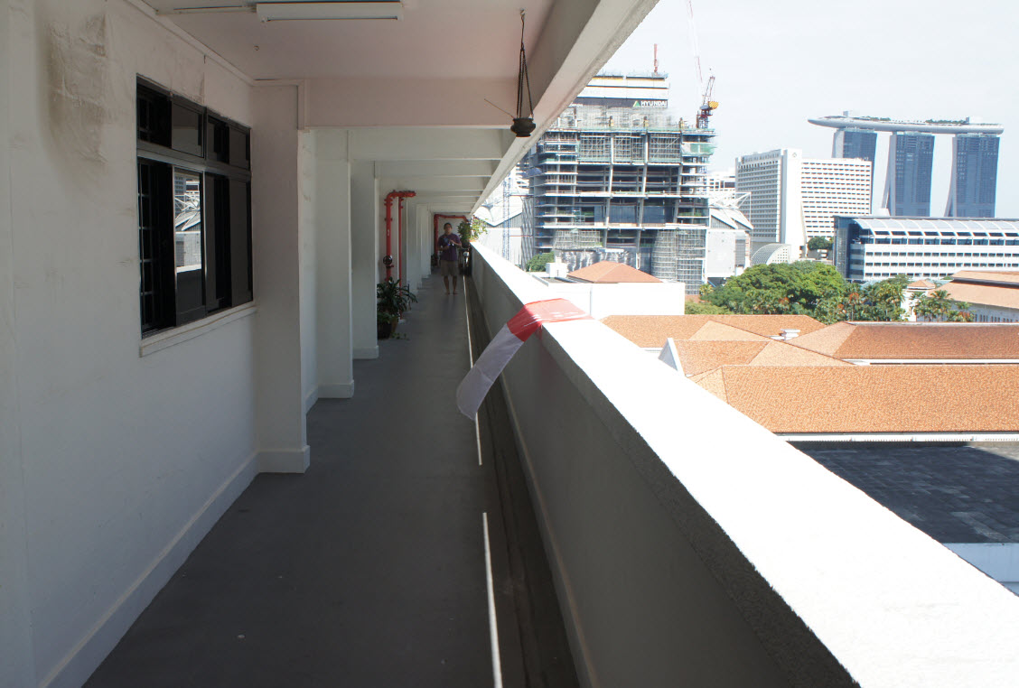
Range: tests show that in straight-line ideal conditions, you have about 20-30 meter range, which is about right -- it's just outside of polite yelling distance, and not so far that people too far away are being strobed. The radio does not go through concrete or doors very well. SL will have about +10-20 meter range beyond the locators because it will have a proper whip antenna (+20dBi gain over the loop antenna in the locator). Note that maximum gain is edge-on, not face-on.
Here's about how far I am when I fail to cause strobing in a companion locator with line-of-sight:
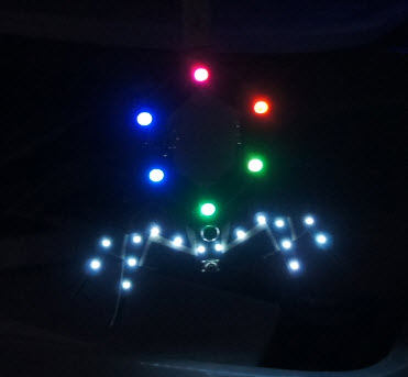
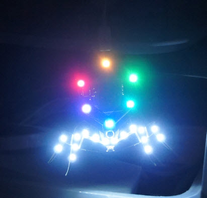
Here's how it actually looks:
5V Farm
The battery packs for the 5V farm are shown below:
The shorter "hydra"-style USB cables for the 5V farm are shown below:
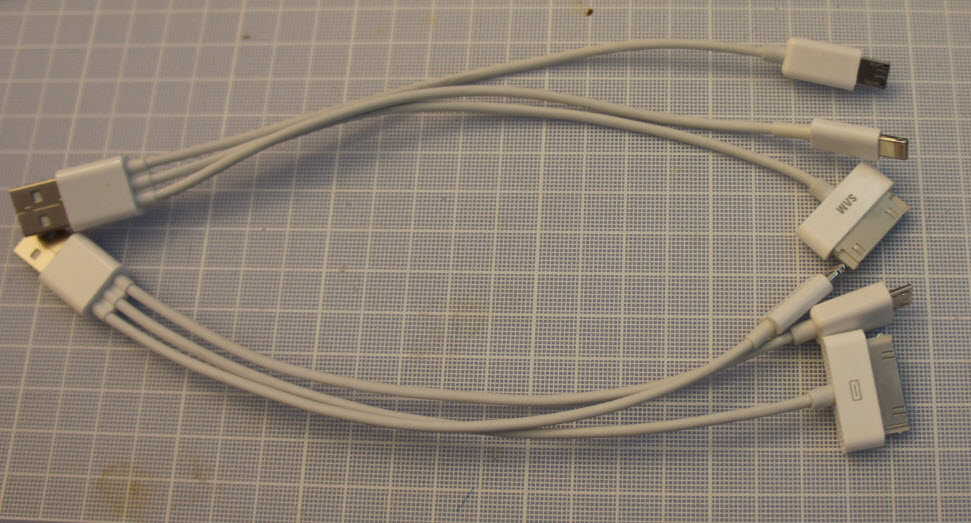
There will also be chargers, regular USB cables, and an artist rendition of the 5V farm courtesy of Christina and Ace.