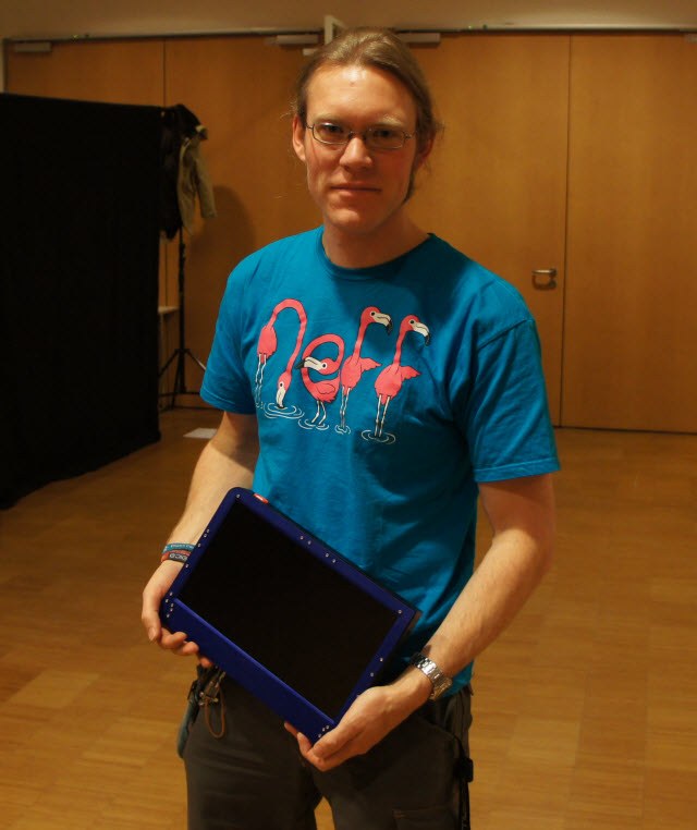
Laptop User Guide
Contents
Don't do This
Most of you don't read user guides. But if there is one thing you should be aware of, it's this:
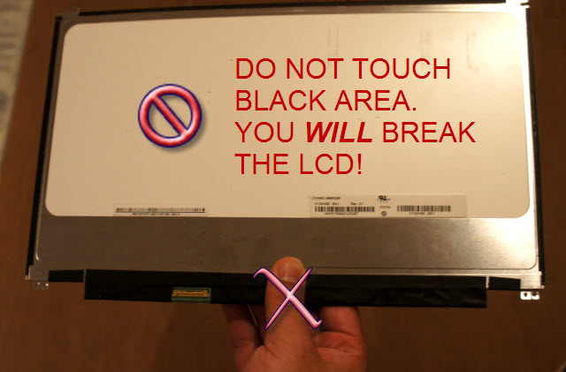
The black, taped area of the LCD is extremely fragile. It contains the TCON and other driver circuitry, and it's a PCB that's bonded directly to the LCD's glass. That bond is very weak. If you flex the PCB, even slightly, you will delaminate the PCB, and you will be very sad. Your LCD will not work.
Do this Instead
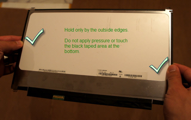
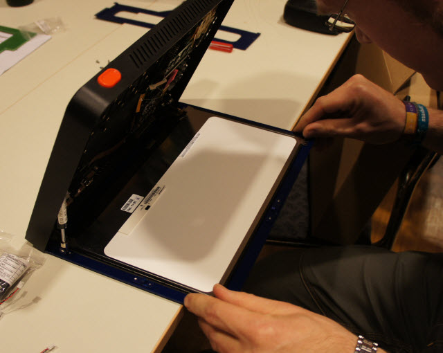
Do hold the LCD from the edges.
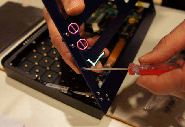
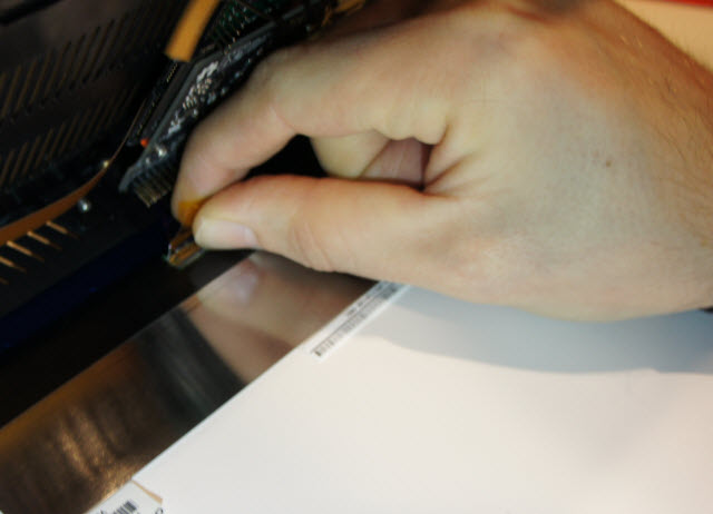
You'll note that rather inconveniently, the connector for the LCD cable is on the black area you're not supposed to flex. Here's how you very carefully insert the connector:
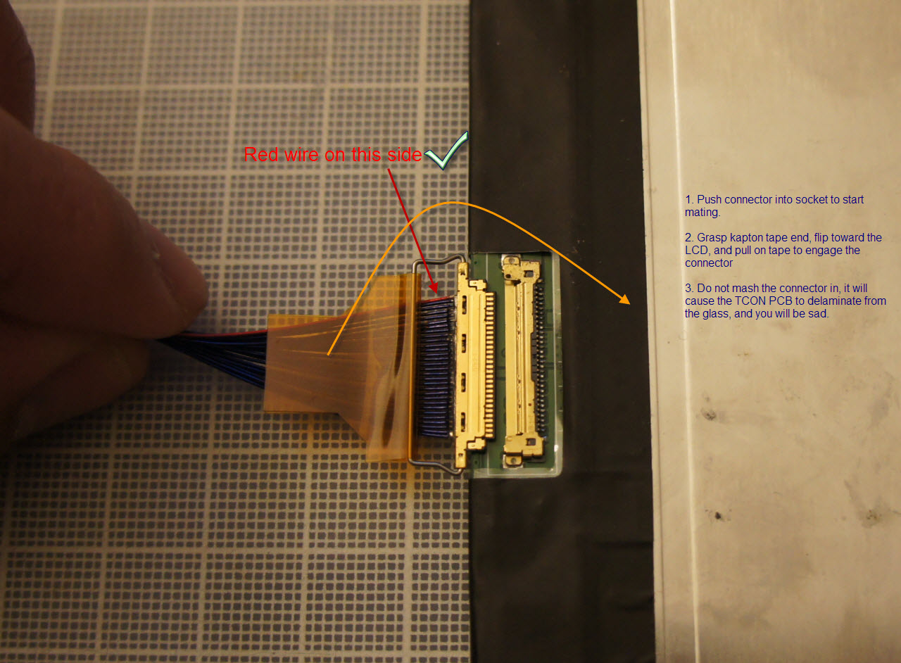
Make sure you have the correct pin 1 orientation. The connector looks very similar from both sides, and the metal bar for pulling the connector in place can be swiveled around so both sides "look" right, if that's what you're going by. Pay attention to the red wire instead.
The force required for insertion when the connector is properly aligned is fairly light; a gentle tug is all it takes. Don't pull the insertion bar with a force perpendicular to the board; pull parallel, as much as possible, to the connector insertion direction.
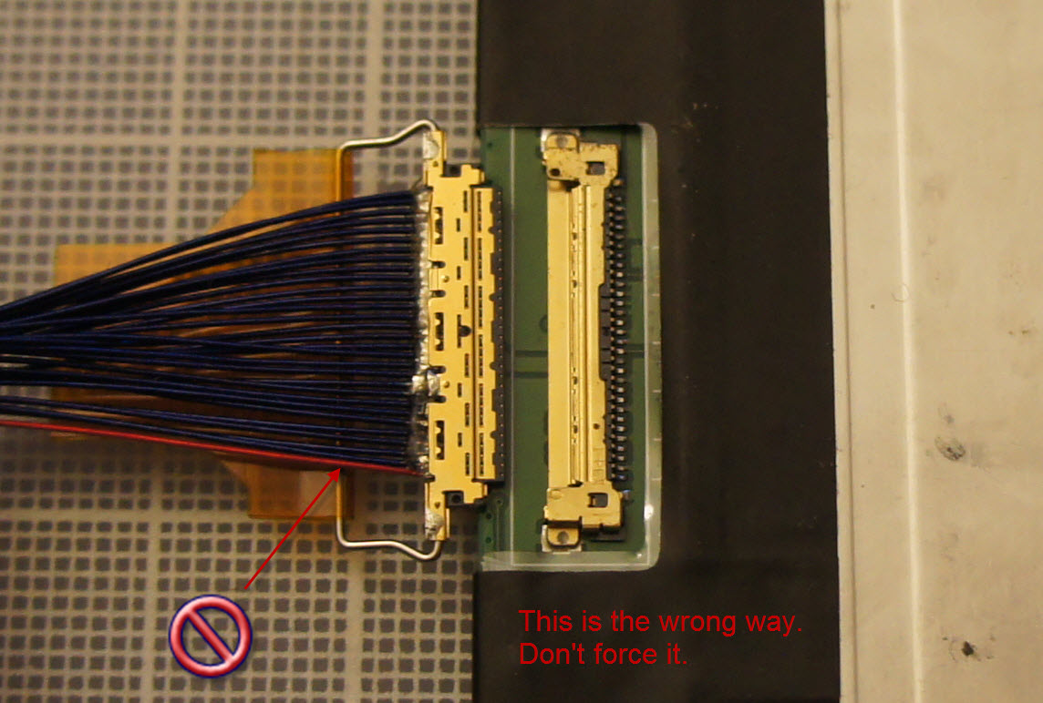
This is the wrong way for the connector, just so you know what it looks like.
Assembly Guide
Here's how you assemble your desktop unit. These steps also apply to the laptop unit.
Opening the box
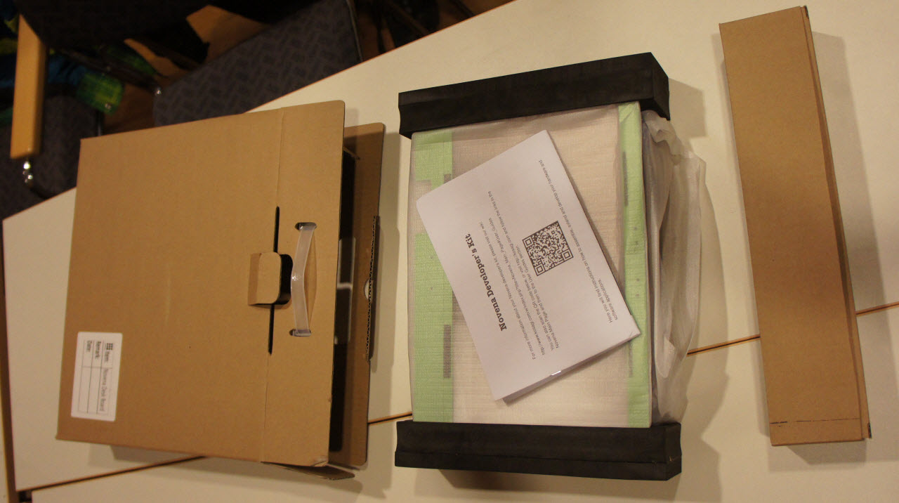
Take all the contents out of the shipping box. There will be a box of accessories, and a padded carrier containing the base unit, LCD, and secondary LCD bezel.
Accessories
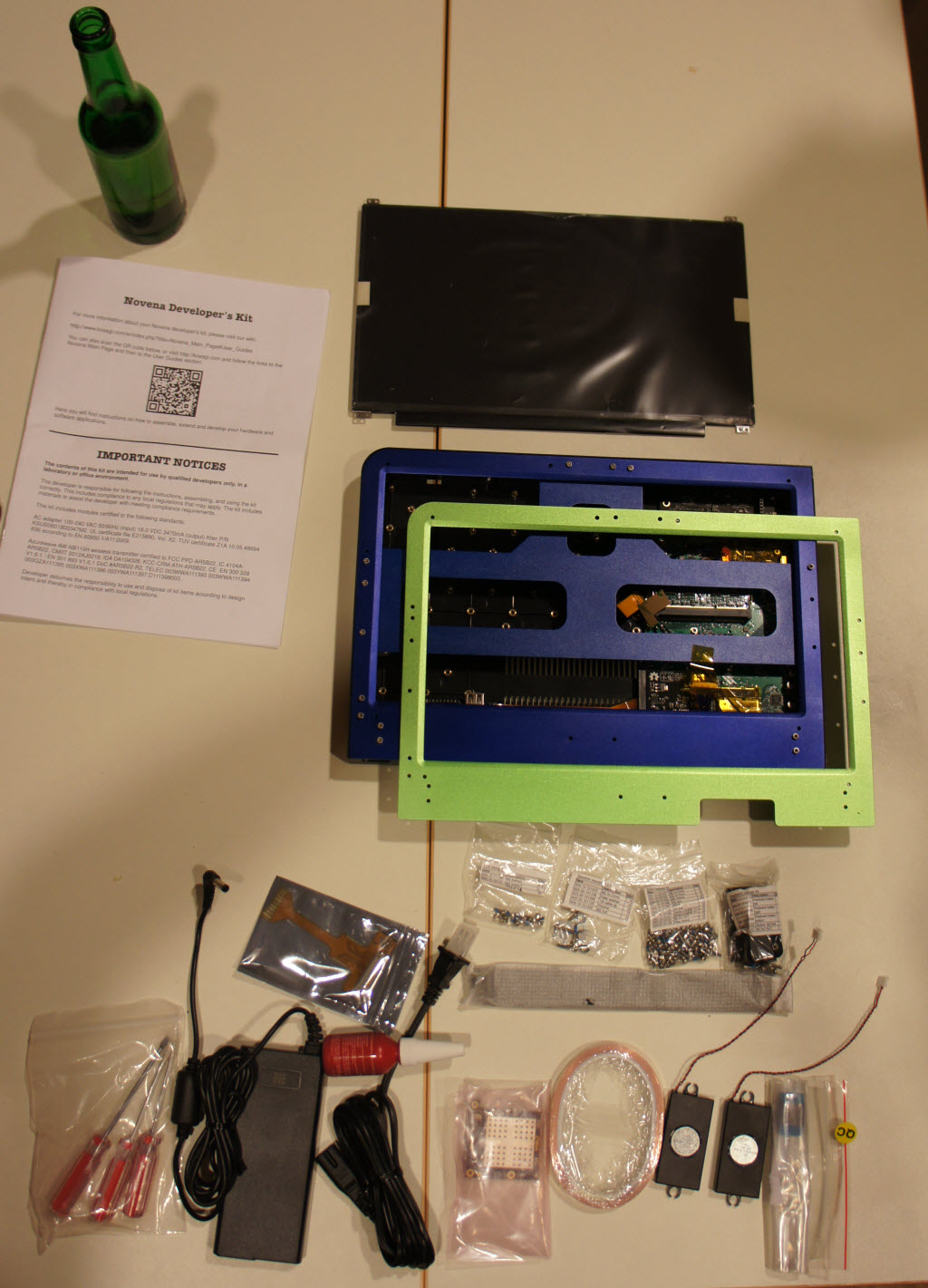
The green bezel is provided for those who need extra access to the expansion slot when the case is closed. It's also a good spot to prototype any changes you want to make to the bezel, e.g. drilling extra holes for buttons and/or connector mounts.
There's a lot of accessories included. Some of the accessories, such as the copper tape, are provided to assist with achieving regulatory compliance, as mandated by your local regulations as the builder of your kit. The loctite is handy for keeping screws in that tend to work their way out. Most of the screws come with a spot of loctite pre-applied, but it never hurts to have extra loctite on-hand, particularly for devices that are exposed to a lot of vibration.
Beer sold separately.
Screwdrivers
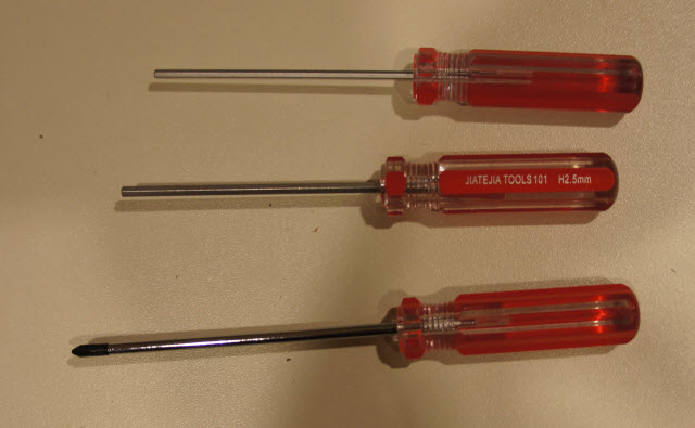
Yes, you're going to need these. Feel free to use your own if you have them.
As for the screw kit, some of the kits contain M2.5x4 screws for the LCD mounting. These may be too short, and so you'll want to use the M2.5x6 screws included in the extra screw bag to make things easier. As a running change, we swapped in M2.5x5 screws, but some of the first shipments may have the shorter screws in the display mounting bag.
LCD Bracket: Removal
First step is to remove the LCD bracket. Only a partial set of three screws is used to hold the bracket in place during shipping. In particular, note that the two top screws on the left side actually hold the the bezel actuator hook in place, so you don't need to remove those.
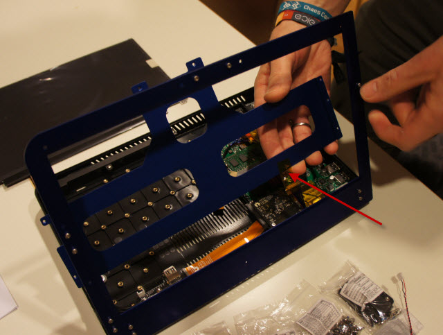
Once you've got the screws out, the bracket should come out nice and easy. You may need to remove a piece of tape securing the LCD cable to the bracket for shipping, called out with a red arrow.
Note: if you want to use the green bezel, this is a good step to swap it in. Please note that you'll also need to transplant the latching mechanism and magnet (located in the top center of the bezel) as well at this point. The magnet is required to get the lid detect switch to work.
LCD protective film
You'll want to remove the protective film on the LCD prior to assembling it.
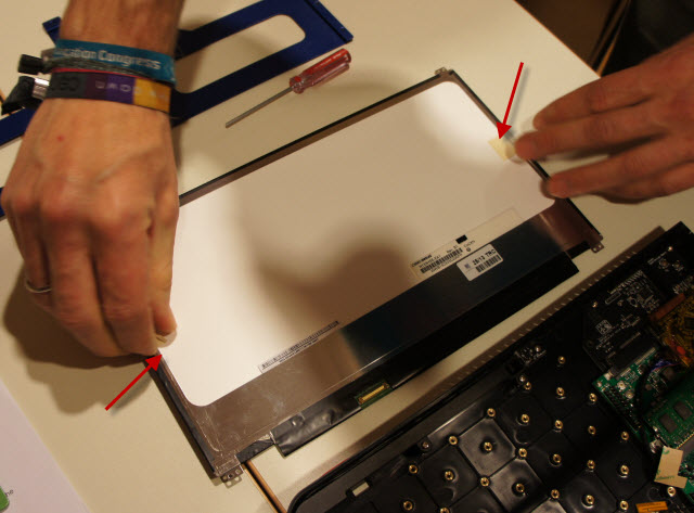
Holding the LCD only by the edges, place it face down on a table, and remove the masking tape from the edges.
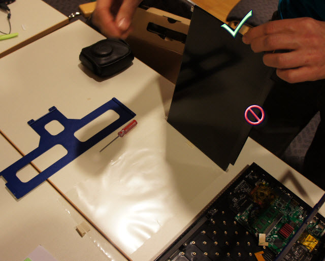
Lift the LCD off from its protective film, again, holding only by the edges.
LCD Installation
Position the unit so that the bezel is face-down to the work surface and hanging slightly off the table, as shown. Lay the LCD into place onto the bezel.
Carefully position the LCD so that the holes in the mounting tabs line up with the holes in the bezel. Only the outer holes on the tabs are used.
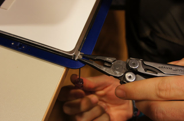
Attach the top screws of the LCD in place, using the provided nuts. You'll probably need a pair of pliers to hold the nut, as the loctite on the screws make it hard to hand-tighten the nut. Don't over-tighten: over-tightening will cause the edges of the screen to blanche. Use the loctite to help keep the screws in place. Repeat for each of two sides.
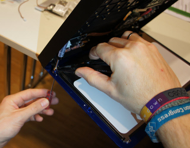
Position the unit as shown above, so that you can access the lower screws. Attach the bottom screws of the LCD in place, using the provided nuts. Repeat for each of two sides. Don't over-tighten.
Cable installation
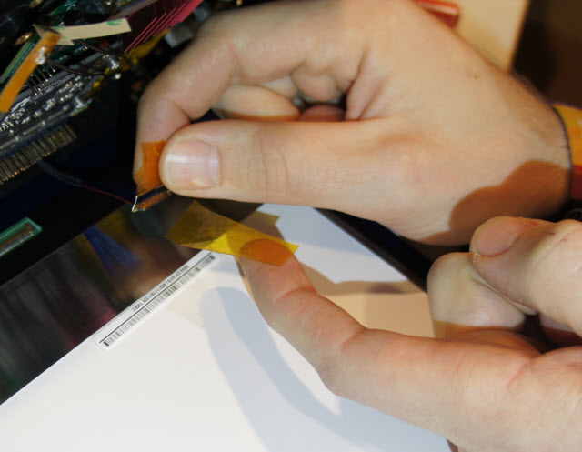
Remove the temporary fastening tape from the connector, if there is any at all. Do not remove the tape permanently attached to the connector pull bar. The temporary fastening tape is tacky on one side, whereas the pull bar tape has no exposed adhesive.
Insert the cable, keeping mind of the polarity, and the warnings stated above, and repeated here again for your convenience.
Make sure you have the correct pin 1 orientation. The connector looks very similar from both sides, and the metal bar for pulling the connector in place can be swiveled around so both sides "look" right, if that's what you're going by. Pay attention to the red wire instead.
Attach LCD bracket

Attach the LCD rear mounting bracket. This requires 7 screws.
Position antennae
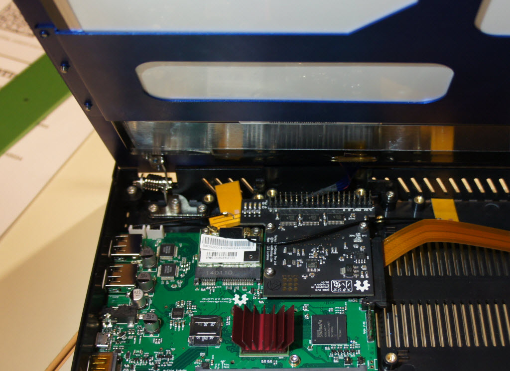
Remove the shipping tape and position the antennae at a location that provides good reception given your setup, and complies to local regulations.
Speakers
This step is optional. If you want to have internal speakers using the provided speakers in the kit, follow these instructions.
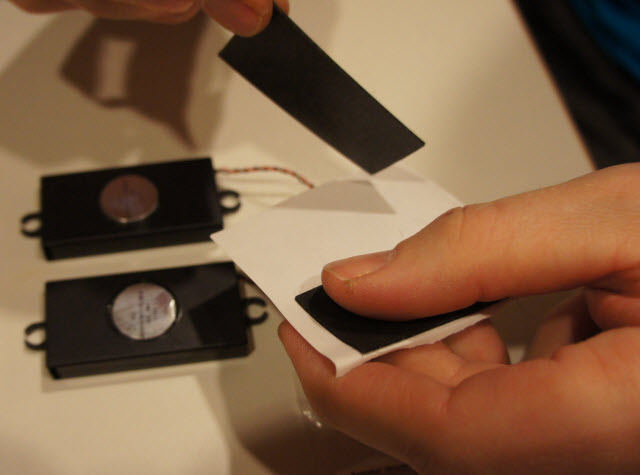
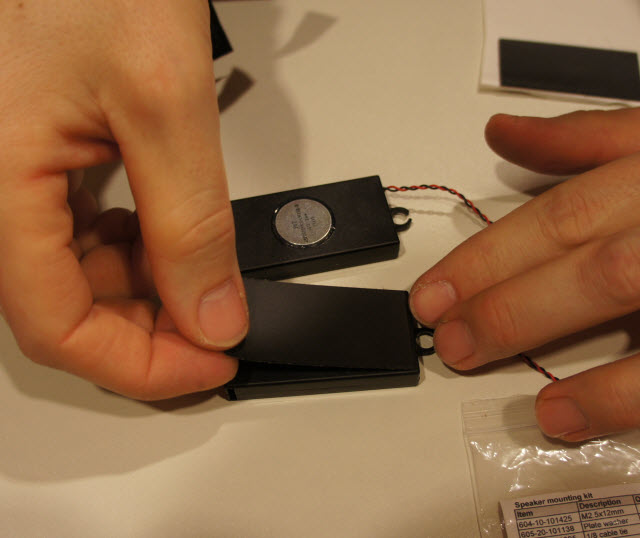
Apply the foam squares to the back side of the speakers. This is optional, but it can help reduce unwanted vibrations.
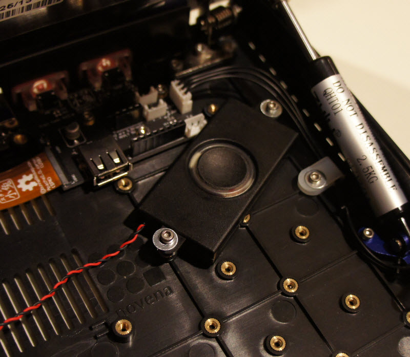
Mount speakers inside the case. There are a pair of bosses on the Peek array which line up quite nicely with the speaker mounting holes when angled correctly.
When mounting, use a washer plus a long screw. You may also want to use a rubber bushing.
Do not over-tighten: just get one side started by a couple of turns, then screw in the other side. Keep going back and forth between the two sides, tightening by a half turn, until each side has about the same amount of force holding the speaker in place. If you crank down too hard, you'll break off the mounting ears and you'll be sad.
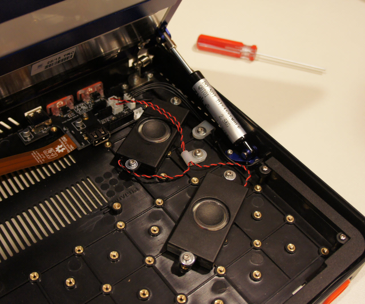
Above is an example of how the speakers can be mounted on the Peek Array. Of course, you should pick the orientation and cable management method that best suits your tastes.
Turn on
When you turn on the unit, the backlight on the LCD should turn on immediately. It will be very obvious from looking at the back of the display. If the backlight doesn't turn on, the LCD cable may not be properly seated. Try re-seating it (gently!) and trying again.
If you install XWindows, you may get some initial problems with palette flicker and intermittent blurry display. These appear to go away when you upgrade all packages and reboot. To upgrade all packages, run `sudo apt-get update && sudo apt-get -y upgrade`.
Acknowledgements
Special thanks to Ole for assembling the very first production Novena Desktop while I hovered over him and took photographs.