Difference between revisions of "Phage"
| Line 1: | Line 1: | ||
| + | __TOC__ | ||
| + | |||
=Phage Band= | =Phage Band= | ||
Revision as of 17:53, 5 July 2013
Contents
Phage Band
The phage band is a small flexible circuit board that's designed to be soldered in a loop of WS2812 RGB LEDs. It is about the size of your thumb.
It's meant to be a convenient and compact way to make a ribbon of LEDs do something interesting.
As of early July, the board has been sent out for fabrication and should be ready well in advance of BM2013.
The board has the following features:
- Powered off of +5V via microUSB header (for use with battery packs commonly used to charge cell phones)
- ATTiny85 for pre-programmed light patterns
- A single pushbutton to control operation mode
- If both ends of the WS2812 ribbon is soldered to the board, the ATTiny85 can automatically detect the length of the LED string
- Microphone and pre-amp with gain control selection (aka "robot heart mode")
- Flex circuit construction
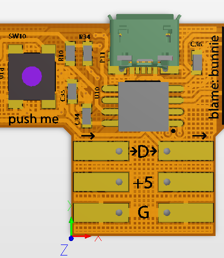
- programming header and microphone section can be sheared off with scissors if they are not needed for a more compact driver circuit
- Steel stiffener plate under ribbon solder point and microUSB header for mechanical robustness
Below are renderings of how the board will look:
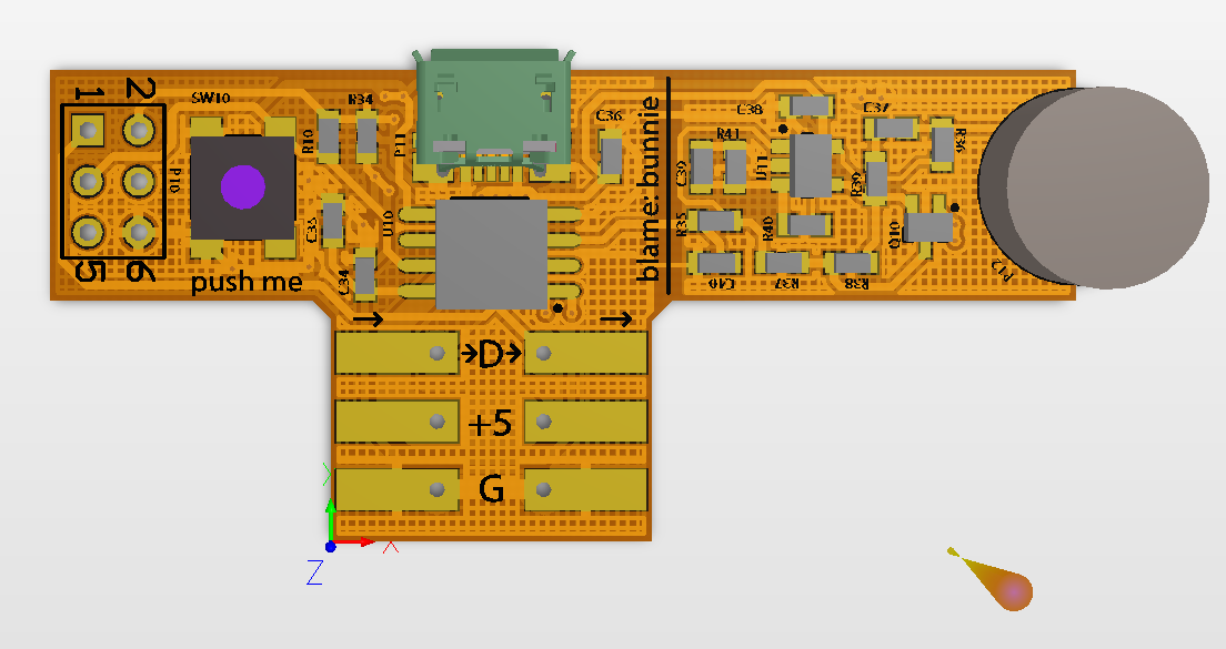
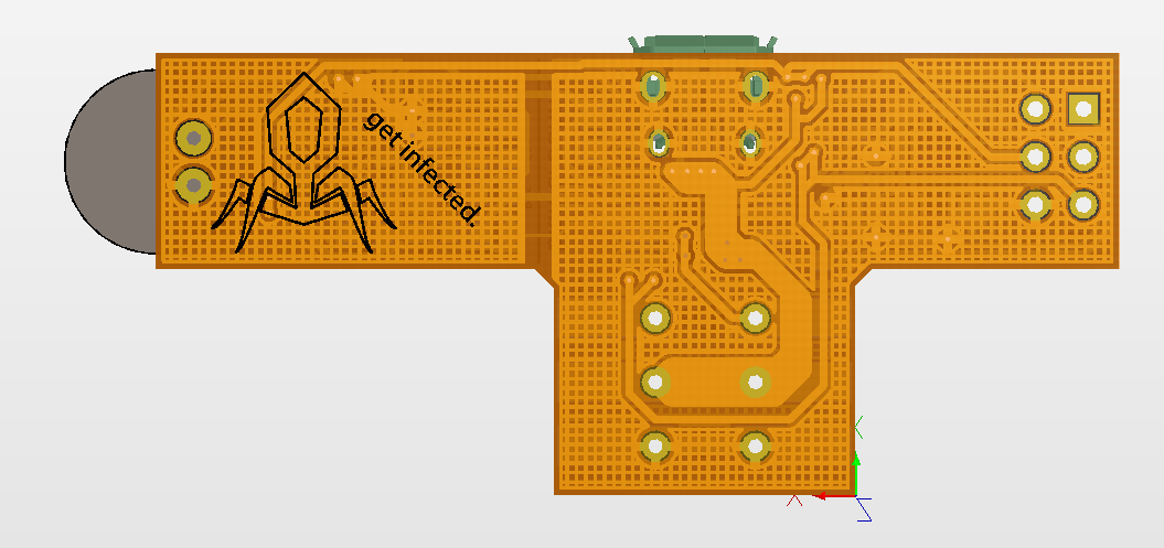
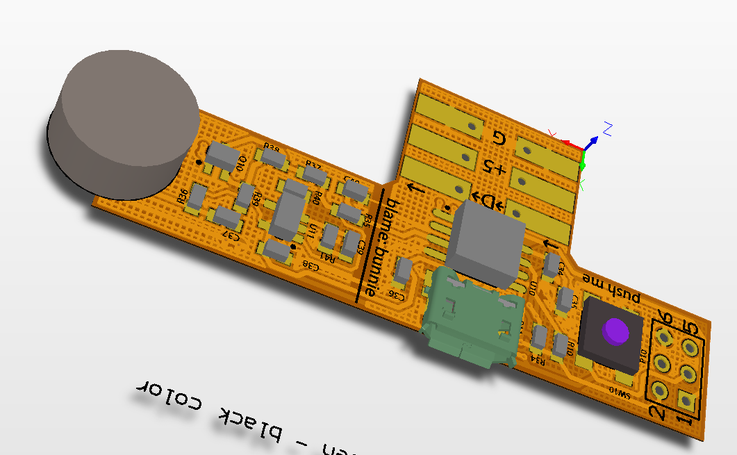
Below is what the board looks like after you've sheared off the microphone and programming headers:
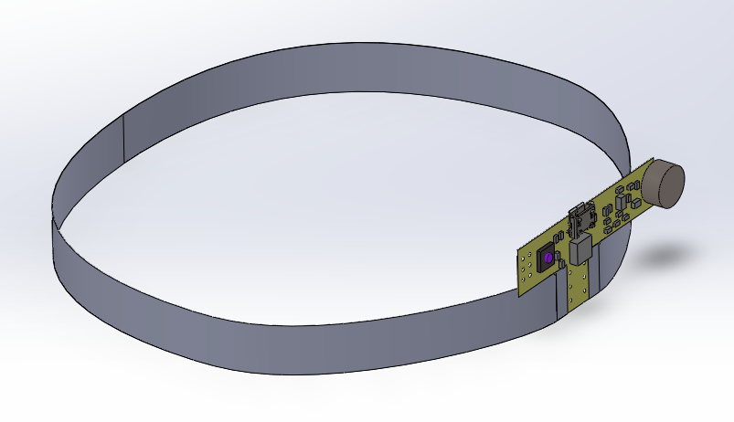
Below is a concept of how the board might look mounted into a ribbon of WS2812 LEDs:
Phage Locator
The phage locator is a design proposal. If enough phagelings are interested, I'll complete the design and get them built.
The idea of the phage locator is it's a little "badge" you can wear around. It has LEDs (of course), and it has a "locate" feature. When the button at the base of the board is pressed, an RF beacon is sent out. Any companions in the vicinity (targeting 20-30m range) will pick up the beacon and start strobing.
When not in locate mode, the board cycles the lights, and may also have a microphone so it can react to sound.
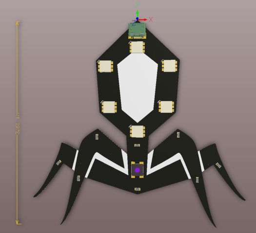
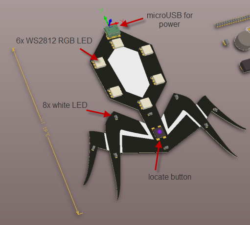
Below are renderings of what the board might look like.
Here is the feature summary:
- Powered off of +5V via micro-USB (compatible with most cell phone battery packs)
- 6 RGB LEDs around the capsid that can cycle indepedently
- 8 white LEDs around the legs that cycle in a "gang"
- RF beacon, activated by pushbutton
- RF receiver - causes strobing action when beacon is detected
- Microphone to cause lights to cycle in the presence of sound (maybe)
- With a sufficiently modest light cycling pattern, it should last days on a typical cell phone charging battery pack
- ~3.6" tall
- Made out of thin FR-4 PCB - semi-rigid
- Matte black soldermask with white silkscreen, gold trim